Search within site
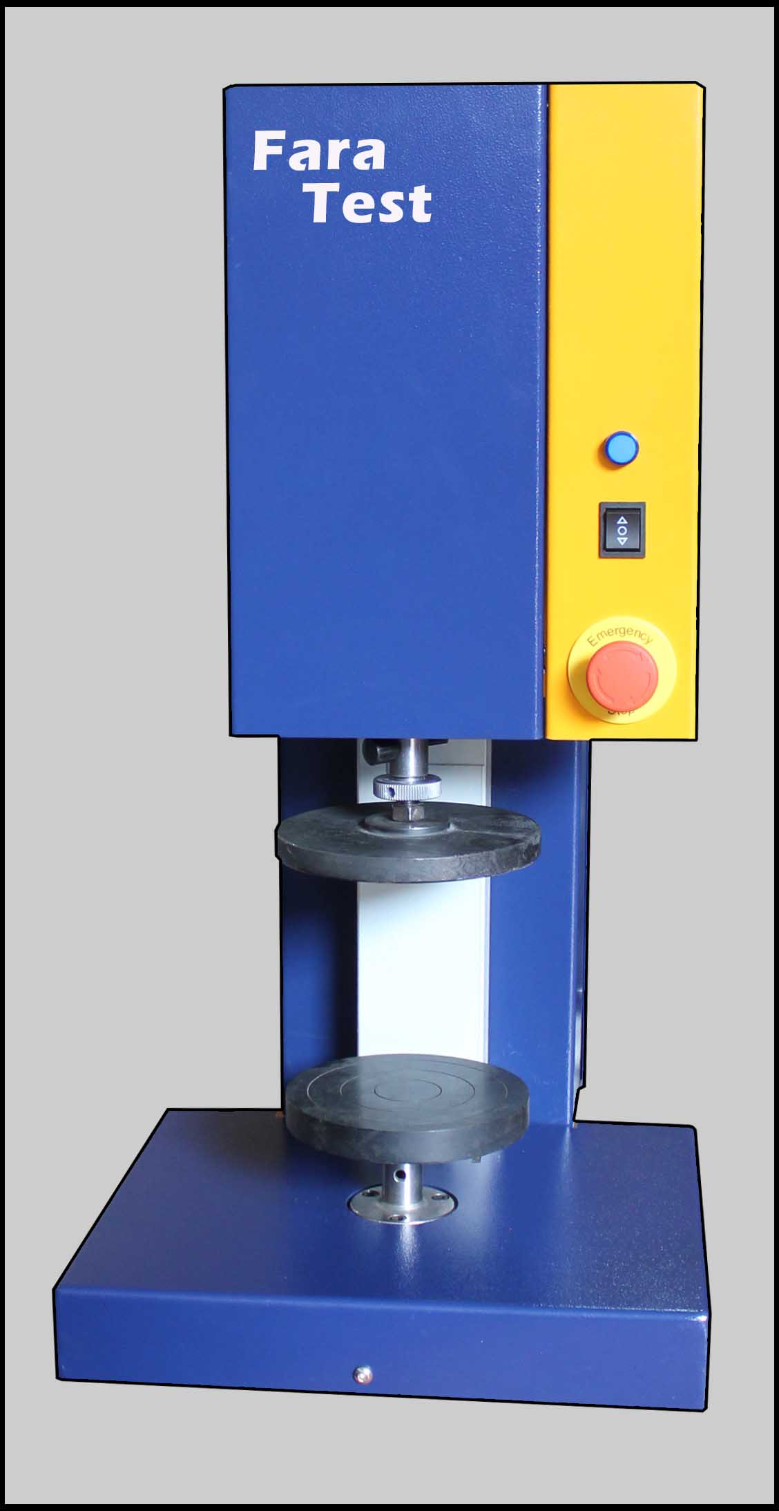
ISO 604 Plastics Determination of compressive properties Testing Machine
- Home
- ISO 604 Plastics Determination of compressive properties Testing Machine

ISO 604:2002(en)
Plastics — Determination of compressive properties
This International Standard specifies a method for determining the compressive properties of plastics under defined conditions. A standard test specimen is defined but its length may be adjusted to prevent buckling under load from affecting the results. A range of test speeds is included.
The method is used to investigate the compressive behaviour of the test specimens and for determining the compressive strength, compressive modulus and other aspects of the compressive stress/strain relationship under the conditions defined.
The method applies to the following range of materials:
-
— rigid and semi-rigid [1] thermoplastic moulding and extrusion materials, including compounds filled and reinforced by e.g. short fibres, small rods, plates or granules in addition to unfilled types; rigid and semi-rigid thermoplastic sheet;
-
— rigid and semi-rigid thermoset moulding materials, including filled and reinforced compounds; rigid and semi-rigid thermoset sheet;
-
— thermotropic liquid-crystal polymers.
In agreement with ISO 10350-1 and ISO 10350-2, this International Standard applies to fibre-reinforced compounds with fibre lengths ≤ 7,5 mm prior to processing.
The method is not normally suitable for use with materials reinforced by textile fibres (see references [2] and [5]), fibre-reinforced plastic composites and laminates (see [5]), rigid cellular materials (see [3]) or sandwich structures containing cellular material or rubber (see [4]).
The method is performed using specimens which may be moulded to the chosen dimensions, machined from the central portion of a standard multipurpose test specimen (see ISO 3167) or machined from finished or semi-finished products such as mouldings or extruded or cast sheet.
The method specifies preferred dimensions for the test specimen. Tests which are carried out on specimens of different dimensions, or on specimens which are prepared under different conditions, may produce results which are not comparable. Other factors, such as the test speed and the conditioning of the specimens, can also influence the results. Consequently, when comparable data are required, these factors must be carefully controlled and recorded.
2 Normative references
The following normative documents contain provisions which, through reference in this text, constitute provisions of this International Standard. For dated references, subsequent amendments to, or revisions of, any of these publications do not apply. However, parties to agreements based on this International Standard are encouraged to investigate the possibility of applying the most recent editions of the normative documents indicated below. For undated references, the latest edition of the normative document referred to applies. Members of ISO and IEC maintain registers of currently valid International Standards.
- ISO 291:1997, Plastics — Standard atmospheres for conditioning and testing
- ISO 293:1986, Plastics — Compression moulding test specimens of thermoplastic materials
- ISO 294-1:1996, Plastics — Injection moulding of test specimens of thermoplastic materials — Part 1: General principles, and moulding of multipurpose and bar test specimens
- ISO 295:—), Plastics — Compression moulding of test specimens of thermosetting materials
- ISO 2602:1980, Statistical interpretation of test results — Estimation of the mean — Confidence interval
- ISO 2818:1994, Plastics — Preparation of test specimens by machining
- ISO 3167:—), Plastics — Multipurpose test specimens
- ISO 5893:—), Rubber and plastics test equipment — Tensile, flexural and compression types (constant rate of traverse) — Specification
- ISO 10724-1:1998, Plastics — Injection moulding of test specimens of thermosetting powder moulding compounds (PMCs) — Part 1: General principles and moulding of multipurpose test specimens
3 Terms and definitions
For the purposes of this International Standard, the following terms and definitions apply (see also Figure 1).
3.1
gauge length
L0
initial distance between the gauge marks on the central part of the test specimen
Note 1 to entry: It is expressed in millimetres (mm).
3.2
test speed
v
rate of approach of the plates of the test machine during the test
Note 1 to entry: It is expressed in millimetres per minute (mm/min).
3.3
compressive stress
σ
compressive load, per unit area of original cross-section, carried by the test specimen
Note 1 to entry: It is expressed in megapascals (MPa).
Note 2 to entry: In compression tests, the stresses σ and strains ε are negative. The negative sign, however, is generally omitted. If this generates confusion, e.g. in comparing tensile and compressive properties, the negative sign may be added for the latter. This is unnecessary for the nominal compressive strain εc.
3.3.1
compressive stress at yield
σy
first stress at which an increase in strain (see 3.4) occurs without an increase in stress (see Figure 1, curve a, and note 2 to 3.3)
Note 1 to entry: It is expressed in megapascals (MPa).
Note 2 to entry: It may be less than the maximum attainable stress.
3.3.2
compressive strength
σM
maximum compressive stress sustained by the test specimen during a compressive test (see Figure 1 and note 2 to 3.3)
Note 1 to entry: It is expressed in megapascals (MPa).
3.3.3
compressive stress at break (rupture)
σB
compressive stress at break of the test specimen (see Figure 1 and note 2 to 3.3)
Note 1 to entry: It is expressed in megapascals (MPa).
3.3.4
compressive stress at x % strain
σx
stress at which the strain reaches a specified value x % (see 3.5)
Note 1 to entry: It is expressed in megapascals (MPa).
Note 2 to entry: The compressive stress at x % strain may be measured, e.g., if the stress/strain curve does not exhibit a yield point (see Figure 1, curve b, and note 2 to 3.3). In this case, x is taken from the relevant product standard or agreed upon by the interested parties. In any case, x will have to be lower than the strain at compressive strength.
3.4
compressive strain
ε
decrease in length per unit original gauge length L0 [see 10.2, equation (6), and note 2 to 3.3]
Note 1 to entry: It is expressed as a dimensionless ratio or percentage (%).
3.5
nominal compressive strain
εc
decrease in length per unit original length L of the test specimen [see 10.2, equation (8)]
Note 1 to entry: It is expressed as a dimensionless ratio or percentage (%).
3.5.1
nominal compressive yield strain
εcy
strain corresponding to the compressive stress at yield σy (see 3.3.1)
Note 1 to entry: It is expressed as a dimensionless ratio or percentage (%).
3.5.2
nominal compressive strain at compressive strength
εcM
strain corresponding to the compressive strength σM (see 3.3.2)
Note 1 to entry: It is expressed as a dimensionless ratio or percentage (%).
3.5.3
nominal compressive strain at break
εcB
strain at break of the test specimen
Note 1 to entry: It is expressed as a dimensionless ratio or percentage (%).
3.6
compressive modulus
Ec
ratio of the stress difference (σ2 – σ1) to the corresponding strain difference values (ε2 = 0,002 5 minus ε1 = 0,000 5) [see 10.3, equation (9)]
Note 1 to entry: It is expressed in megapascals (MPa).
Note 2 to entry: The compression modulus is calculated on the basis of the compressive strain ε only (see 3.4).
Note 3 to entry: With computer-aided equipment, the determination of the modulus Ec using two distinct stress/strain points may be replaced by a linear regression procedure applied to the part of the curve between these points.
ISO 472- ISO 3597-3- ISO 7616- ISO 7743- ISO 14126
Faratest Co supplies testing machines
Tel: +98 21 88705040
Whatsapp & Telegram: +98 912 3750274
Contact
- تهران، بزرگراه فتح، فتح 11، گلبن 10 شرقی، پلاک5
- 88705040
- 88705042
- 0912-3750274
- info@faratest.com